Drone survey
- Surveying with a drone offers enormous potential to professionals. With a drone, it is possible to carry out topographic surveys of the same quality as the highly accurate measurements collected by traditional methods in a fraction of the time. This substantially reduces the cost of a site survey and the workload of specialists in the field.
- We have experienced drone operators to capture surface features at a rapid rate for projects where time is a constraint. Advanced post processing software’s that will suit every client need and requirement. We can also integrate DGPS surveys, total station surveys with surveys to incorporate data which may otherwise not be obtainable with aerial photogrammetric survey, so that our clients have seamless continuous & complete information for their planning requirements. Drone Surveys combines the latest advances in Unmanned Aerial Vehicles (UAVs) with innovative uses of imaging equipment to perform a wide range of high quality mapping & aerial surveys. Aerial surveys and mapping from UAVs offer levels of accuracy, precision and details.
Total Stationed Survey
- A total station is a tool used for surveying. The equipment heavily relies on geo-radar and time signals to calculate the levels and distances of points it is set over.
- Customers benefit from the many features of total stations, such as data capturing and analysis. These features allow businesses to take advantage of flawless and accurate survey collecting, providing significant cost savings while increasing the likelihood of getting accurate information.
DGPS Survey
- Traditionally lattice towers common for high voltage transmission lines.
- Use of steel poles started in late 1960s in US with extensive research, engineering and testing in early stages.
- Received wider acceptance in 70s & 80s. Valmont one of pioneers in design and manufacturing.
- Today steel poles are the dominant type structures for new age power transmission & are commonly used in many countries, being adopted in more new markets.
- We are EPC solution provider for design, manufacturing, Supply & Erection of Monopole towers with support of Valmont Structures. Ltd
Steel Pole Foundation Options
Directly Embedded / Isolated / Pier / Pile / Anchor
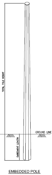

Directly Embedded
 33 kV S/C Pole
 Embedded 220 33 kV S/C Pole

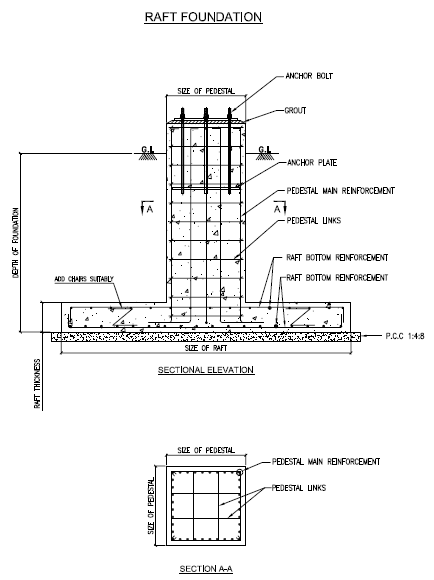
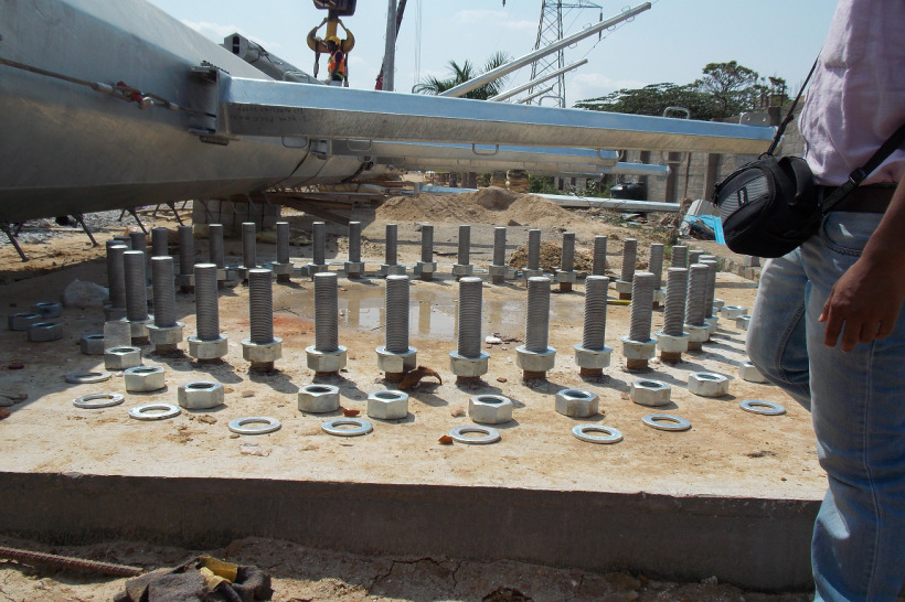
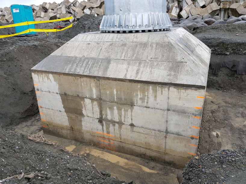
Isolated Foundation (with Anchor Bolts)

 132 kV D/C Pole (Before Casting)
- This may be square, rectangular or circular in plan.
- Rectangular footing may be used in locations where space is restricted and not possible to provide square footing.
 400/220 kV M/C Pole (Before & After
Casting)
400/220 kV M/C Pole (Before & After
Casting)
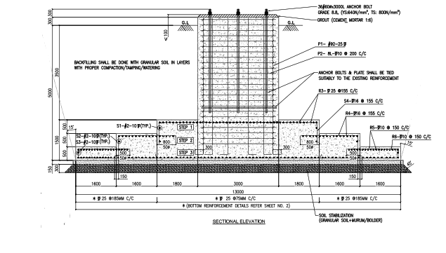
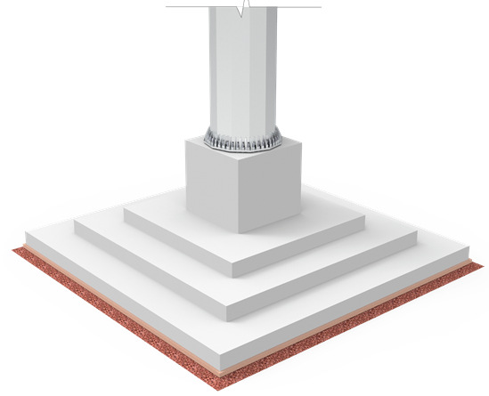
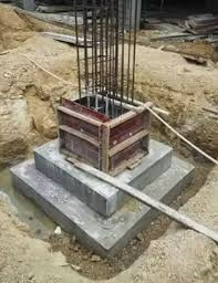
Step Foundation (with Anchor Bolts)
- Stepped (Spread Footing) solution is optimised version of Isolated Foundation
- Approx. 30% saving when compared with the Isolated Foundation.
 Monopole
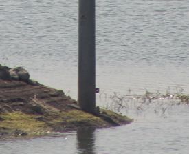
 Actual Site
 Double Pole
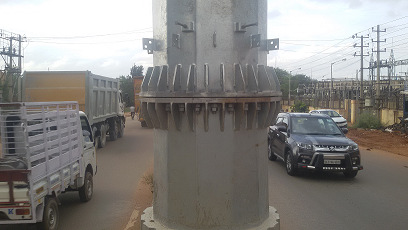
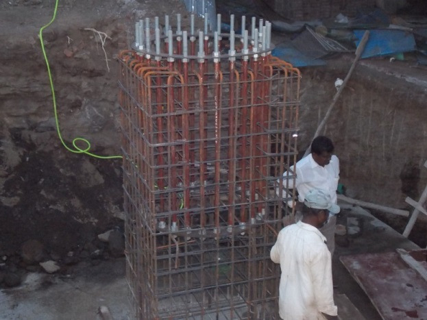
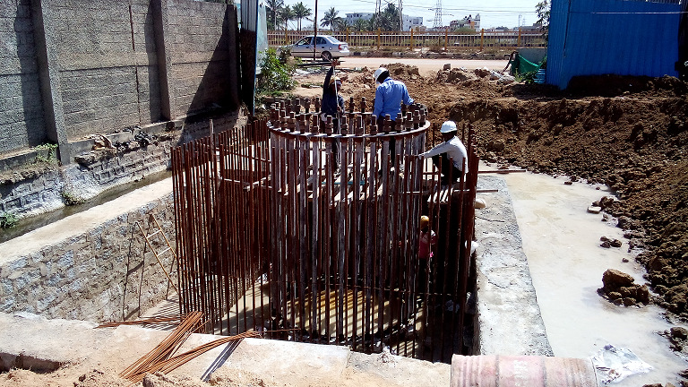
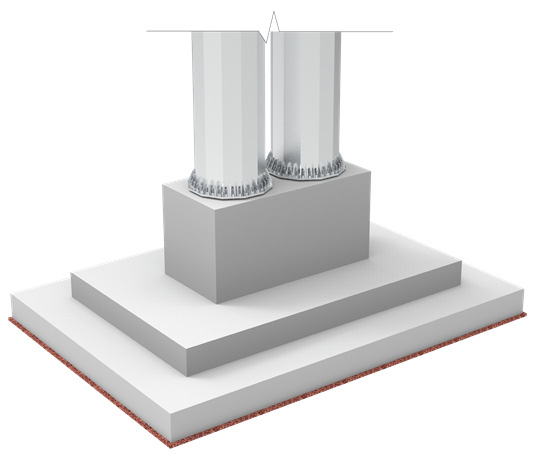
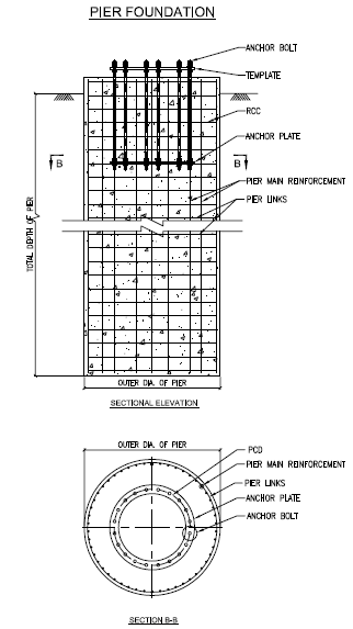
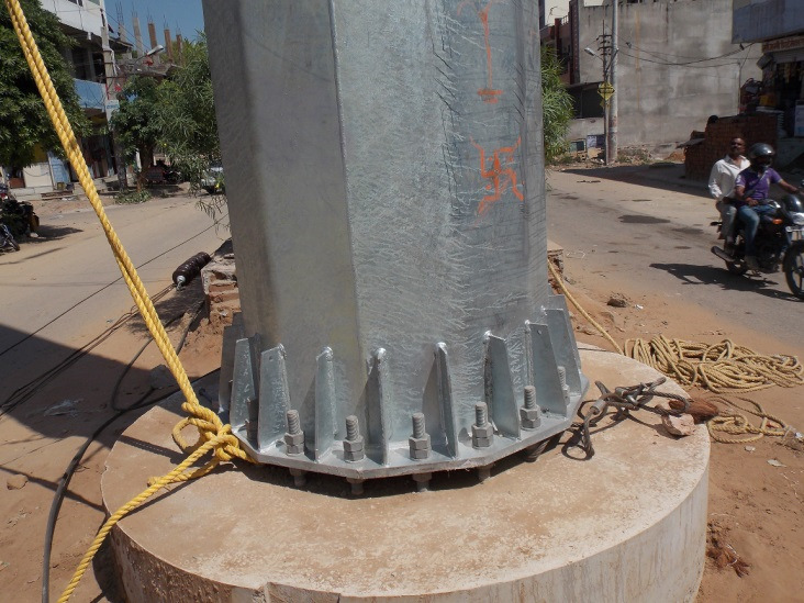
Pier Foundation (with Anchor Bolts)
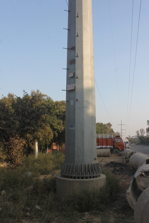 132 kV S/C Pole for UPPTCL
 132 kV D/C Pole for RRVPNL (Before & After
Casting)
132 kV D/C Pole for RRVPNL (Before & After
Casting)
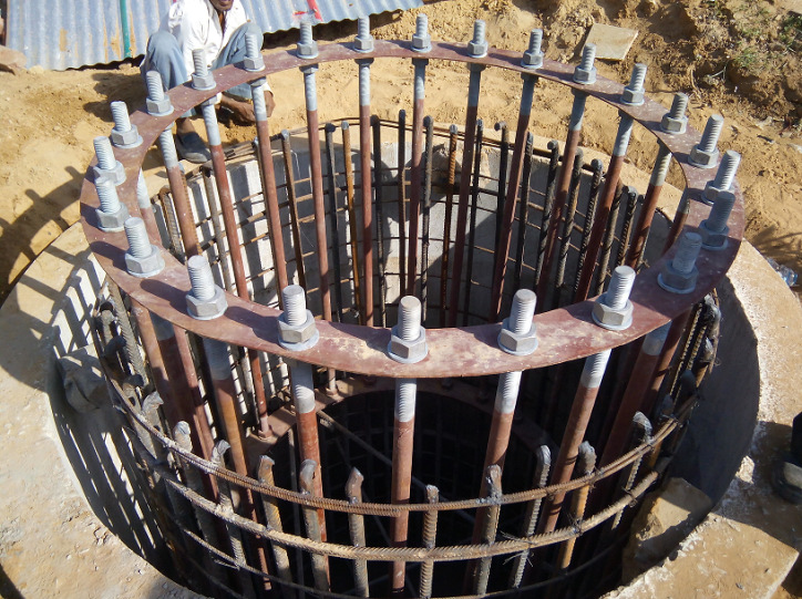
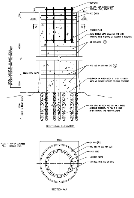
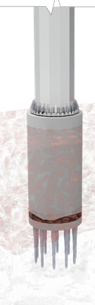
Pier Foundation in Hard Rock (with Anchor Bolts)
- Effective solution for hard rock conditions like Granite, Basalt, etc.
- In hard rock condition main bars can be inserted into the rock using drill holes and adhesive chemicals.
- Bore hole depth approx. 55 times of the diameter of the main bar used for foundation.
- Proper soil investigation and expert opinion suggested before taking such foundation work.
- Review of RQD & CR is important before recommending such design.
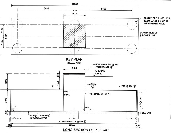
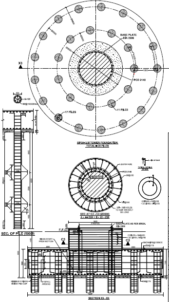
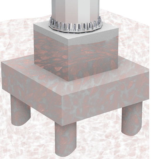
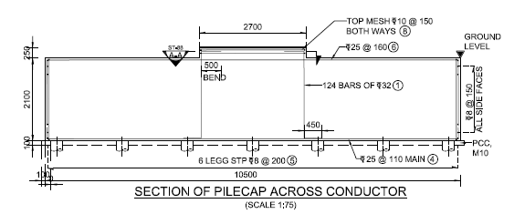
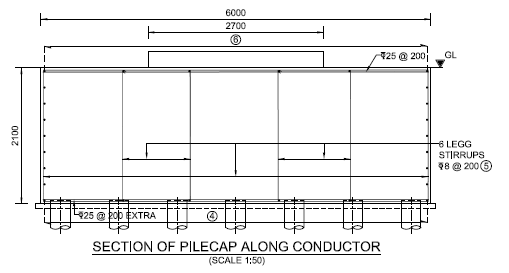
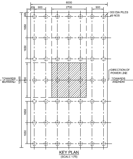
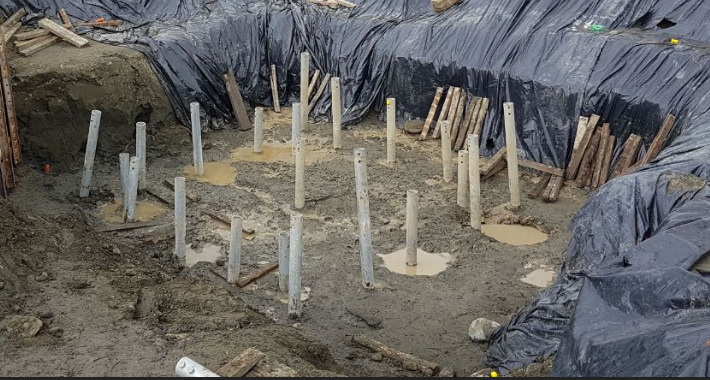
Pile Foundation (with Anchor Bolts)
- Effective solution where other foundations types are not suitable/difficult to construct.
- This type of foundation used at Coastal belts, Near Rivers and where poor soil strata is available.
- Heavy moments will transfer to larger depth through piles, hence heavy moment carrying capacity.
- Effective solution with narrow foot print.
- Pile diameter and depth varies with the soil conditions.
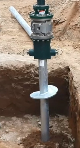
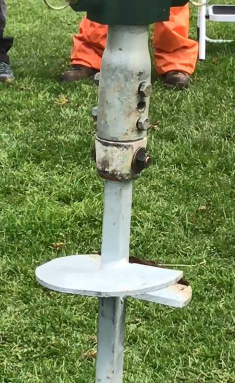
Micro Pile Foundation (with Anchor Bolts)
- Pile foundation for difficult site conditions with space constraints.
- Pile diameter and depth varies with the soil conditions of site.
Anchor Foundation (with Anchor Bolts)
- Effective solution for quick preparation of foundations.
- Anchor type and depth varies with the soil conditions.
Monopole tower
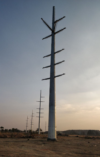 220/132 kV M/C Pole, RRVPNL
- Section joining arrangements
- Climbing arrangements
- Anticlimbing arrangements
- Cross arm arrangements
 400/220 kV M/C Pole, KPTCL
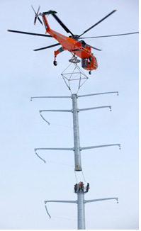 Installation by Heli Crane
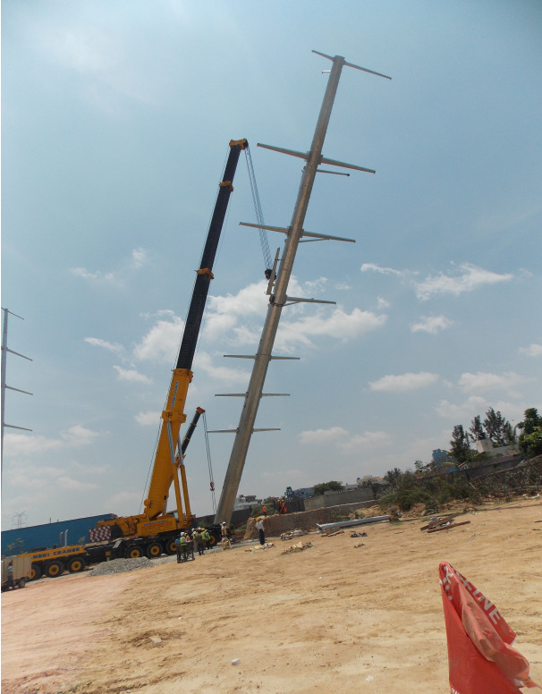
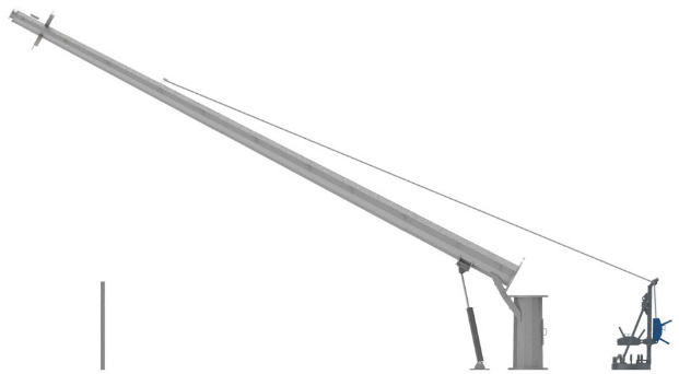
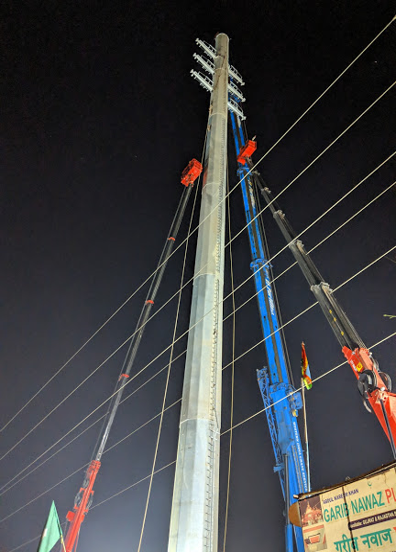
Installation Options
- Option - 1 with suitable crane, after complete pole assembled horizontally on the ground.
- Option - 2 with suitable cranes, section by section assembled vertically.
- Option - 3 with suitable derrick, section by section assembled vertically.
- Option - 4 & 5 with suitable jacks or hoist winch attached to the poles foundation.
 400/220 kV M/C Pole, KPTCL
 220 kV D/C Pole, DMRC/DTL
 110 kV D/C Pole, KSEB
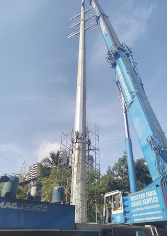
Monopole Erection & Site Photographs
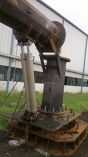
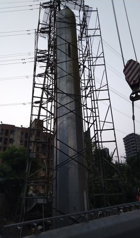 Assembled Scaffolding around 1st section of
Monopole
Assembled Scaffolding around 1st section of
Monopole
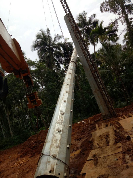
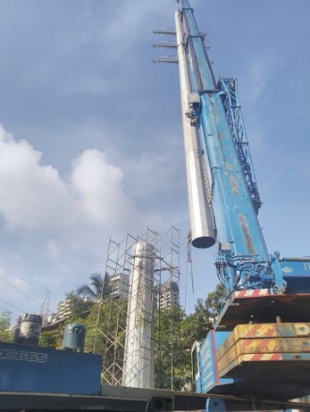 2nd section lifting with crane
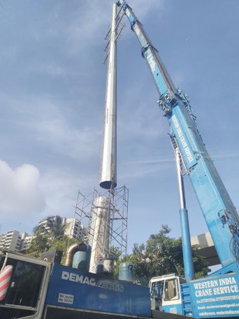 3rd stage alignment of sections.
 4th stage insertion using scaffolding.
 Using Man lifter
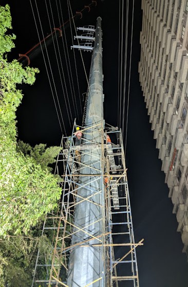 Using Scaffolding
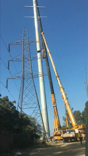
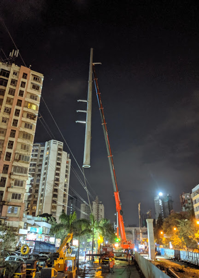 Assembled Monopole erection in single piece
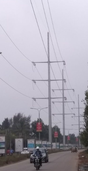
Lattice tower
- Traditionally lattice towers common for high voltage transmission lines.
- Use of steel poles started in late 1960s in US with extensive research, engineering and testing in early stages.
- Received wider acceptance in 70s & 80s. Valmont one of pioneers in design and manufacturing.
- Today steel poles are the dominant type structures for new age power transmission & are commonly used in many countries, being adopted in more new markets.
- We are EPC solution provider for design, manufacturing, Supply & Erection of Monopole towers with support of Valmont Structures. Ltd
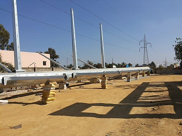
Substation structures
- A substation is a part of an electrical generation, transmission, and distribution system. Substations transform voltage from high to low, or the reverse, or perform any of several other important functions. In between the generating station and consumer, electric power may flow through several substations at different voltage levels. Substations may be owned and operated by an electrical utility, or may be owned by a large industrial or commercial customer.
Stringing / Re Conductering
Conductor stringing systems currently employed in the power industry are almost as numerous as the organizations that string conductors. Below is an outline of the basic methods currently in use, but they are invariably modified to accommodate equipment readily available and the ideas and philosophies of the responsible supervisors. In addition to a description of the various methods being used are comments relative to application and a listing of equipment applicable to each method.
Tension method
- Using this method, the conductor is kept under tension during the stringing process. Normally, this method is used to keep the conductor clear of the ground and obstacles, which might cause conductor surface damage, and clear of energized circuits.
- It requires the pulling of a light pilot line into the travellers, which in turn is used to pull in a heavier pulling line. The pulling line is then used to pull in the conductors from the reel stands using specially designed tensioners and pullers.
- For lighter conductors, a lightweight pulling line may be used in place of the pilot line to directly pull in the conductor. A helicopter or ground vehicle can be used to pull or lay out a pilot line or pulling line.
- The tension method of stringing is applicable where it is desired to keep the conductor off the ground to minimize surface damage or in areas where frequent crossings are encountered. The amount of right-of-way travel by heavy equipment is also reduced.
- Usually, this method provides the most economical means of stringing conductor. The helicopter use is particularly advantageous in rugged or poorly accessible terrain.
- Major equipment required for tension stringing includes reel stands, tensioner, puller, reel winder, pilot line winder, splicing cart, and helicopter or pulling vehicle.
Slack or layout method
- Using this method, the conductor is dragged along the ground by means of a pulling vehicle, or the reel is carried along the line on a vehicle and the conductor is deposited on the ground. The conductor reels are positioned on reel stands or jack either placed on the ground or mounted on a transporting vehicle.
- These stands are designed to support the reel on an arbour, thus permitting it to turn as the conductor is pulled out. Usually, a braking device is provided to prevent overrunning and backlash. When the conductor is dragged past a supporting structure, pulling is stopped and the conductor is placed in travellers attached to the structure before proceeding to the next structure.
- This method is chiefly applicable to the construction of new lines in cases in which maintenance of conductor surface condition is not critical and where terrain is easily accessible to a pulling vehicle. The method is not usually economically applicable in urban locations where hazards exist from traffic or where there is danger of contact with energized circuits, nor is it practical in mountainous regions inaccessible to pulling vehicles.
- Major equipment required to perform slack stringing includes reel stands, pulling vehicle(s), and a splicing cart.
Lisoning
While executing a project we take care of detailed planning and coordinating with the consultants & Utilities requirement. . We plays an important role for the smooth execution and completion of a project. They are appointed to take care of the following services:
- Coordinating between the Sanctioning Authorities
- Follow up with various departments and Government authorities
- Obtaining sanctions for the projects
- Fills the gap between the government offices, construction companies and other related agencies
- Resolving various legal and other issues that are related to construction
Consultancy
- Concept to commissioning Engineering solutions to turnkeys projects of EHV Transmission line.
- Route Survey of EHV transmission lines including profiling and tower spotting, using modern equipment and software.
- Preparation of Tower spotting data with reference to complete final designs.
- Civil, Electrical & Structural Design of L.V, H.V & EHV Switch yards/ Transmission Lines/ Distribution Lines.
- Preparation of Project Report for Electrical installation, Switch yard Transmission/Distribution lines.
- Temporary / Permanent diversion of EHV Transmission Lines for Railway / Road construction.